1.75 MM FDM · LDR ARRAY · CLOSED LOOP
Research system for producing 1.75 mm FDM filament: closed-loop diameter control with an LDR sensor array, thermal validation, drafted IEEE paper.
- LAB
- RIDE @ UTD · Prof. Yonas Tadesse
- STAGE
- ~95% integrated · paper drafted
- SENSING
- 5× LDR + 1 W line laser
- CONTROL
- ESP32 · TMC2209 · 5-level state machine
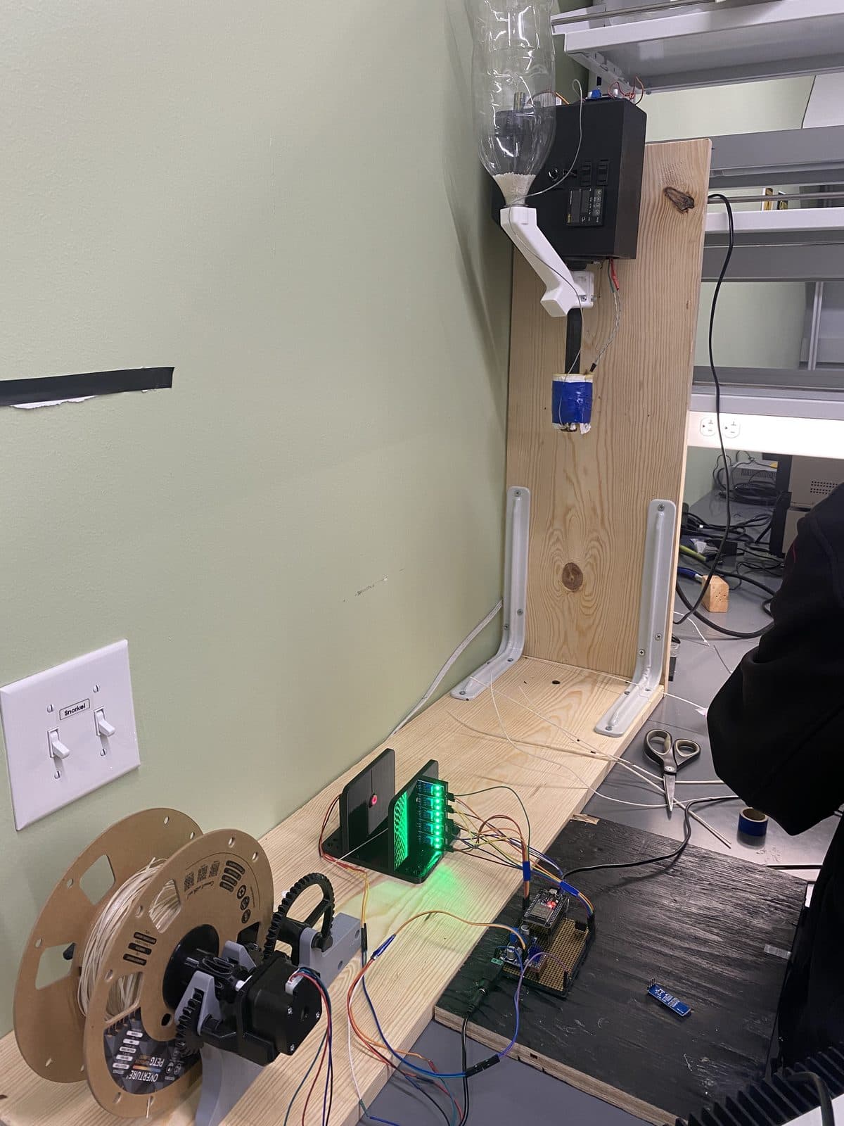
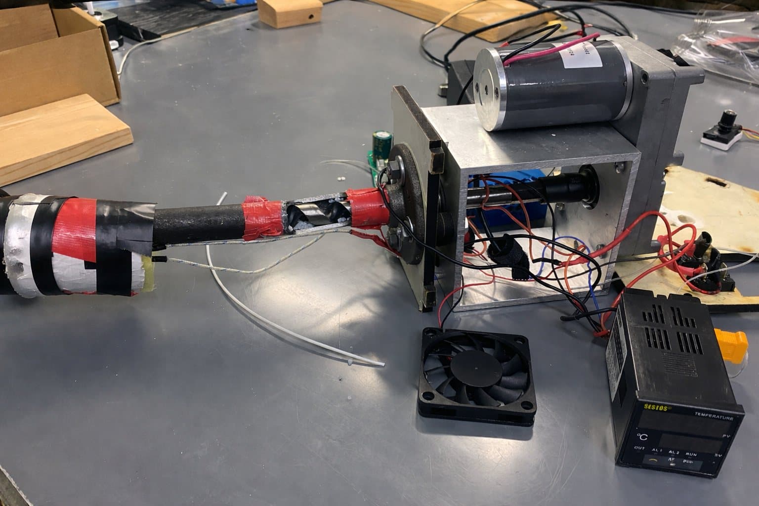
Research labs that need 3D-printed materials are stuck buying commercial filament, which fixes the formulation. The RIDE Lab needs custom filaments for soft-robotics work: magnetic particles, conductive fillers, polymer matrices tuned for embedded actuation. The starting hardware was a partially-functional FilaStruder with a bent extrusion rod, exposed wiring, an unstable horizontal enclosure requiring destructive disassembly, and no winding or sensing, so hot filament piled up on the floor and fused into tangles within minutes of unattended operation.
The rebuild turned it into a closed-loop semi-automated system: a vertically-oriented modular ABS enclosure with sliding panels and pin-header wiring, a custom pellet funnel that threads onto standard plastic bottles, a Pasta-lite-derived winder on a NEMA 17, an array of 5 LDRs paired with a 1 W red line laser for slack detection, and an ESP32 running 5-level state-machine control with debounce, ramping, and explicit fault states. A drafted IEEE-format paper documents the work; diameter-consistency testing is live.
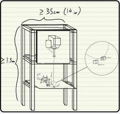
The system was worked out on paper before any CAD. The first concept stacked everything in one 1.5 m tower: extruder on top, winder below. It was abandoned quickly: too much bench footprint, and the frame would have needed purchased structural material that served no other purpose.
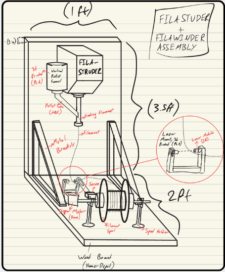
The second sketch became the system: an L-shape. The extruder hangs vertically from a wall-mounted board (why vertical matters is the next section) and the winder sits on the bench beside it. Total purchased material: one board and two brackets. Everything else was 3D printed or recycled from previous projects.
Reorienting a working machine isn’t free; the argument for going vertical became the foundation document of the whole rebuild. It has two parts:
Gravity stabilizes melt flow. Vertical, gravity acts along the flow: screw channels stay filled, hydrostatic pressure in the melt column stays consistent, diameter stays uniform. Horizontal, molten polymer pools at the bottom of the barrel: uneven screw filling, localized pressure variation, air pockets, diameter drift.
Gravity prevents particle segregation, the load-bearing argument for the lab’s research. Magnetic and conductive fillers (iron, ferrite, rare-earth powders, carbon) are several times denser than molten thermoplastic. Horizontal, they sink and the filament comes out particle-rich on one side, fatal for magnetic soft-robotic actuators, whose response depends directly on filler concentration. Vertical, there is no “sideways” for heavy particles to migrate to: the mixture stays axially uniform to the die.
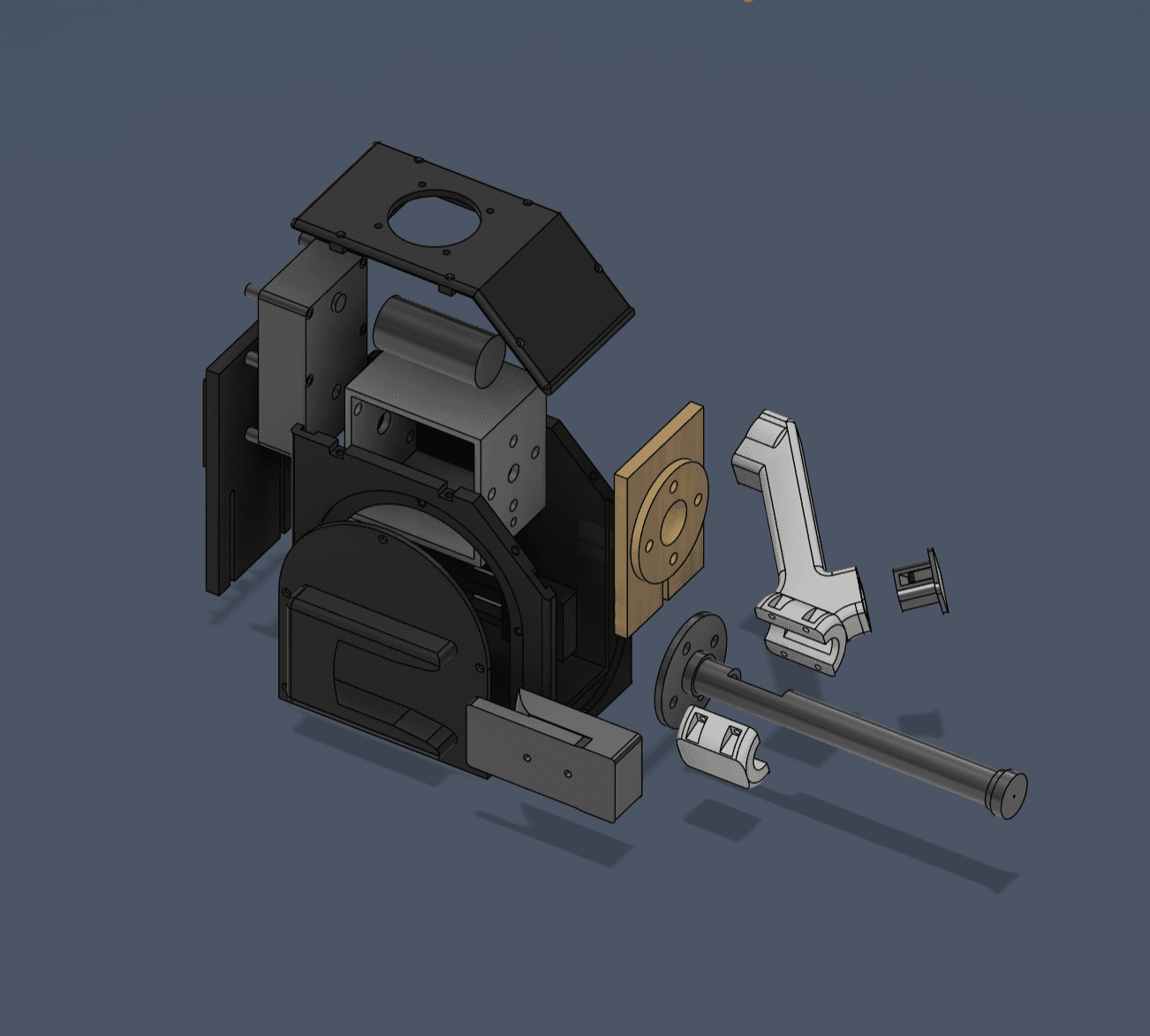
The enclosure went through three documented casing iterations, each driven by fit-test failures of the last: caliper-measured dimensions, corrected bottle-thread direction, arch-reinforced prints, and a trap-door pellet drain by iteration three. Four properties held throughout:
| PROPERTY | IN PRACTICE |
|---|---|
| Modularity | Interchangeable slide-in panels: any panel reprintable without touching the rest |
| Accessibility | Removable panels replace the destructive disassembly the original required |
| Maintainability | Casing slits let panels slide over existing wires; pin headers everywhere: zero-cutting maintenance |
| Vertical mounting | Wall-mount side fixture; whole assembly slides in/out as one unit, gravity-aligned |
The pellet funnel is a dedicated three-piece component: a bottle-threaded mouth (any standard plastic bottle becomes a transparent, replaceable reservoir), and the trap-door drain that makes material switching clean: no picking pellets out by hand, no cross-contamination between a PLA run and a magnetic-composite run.
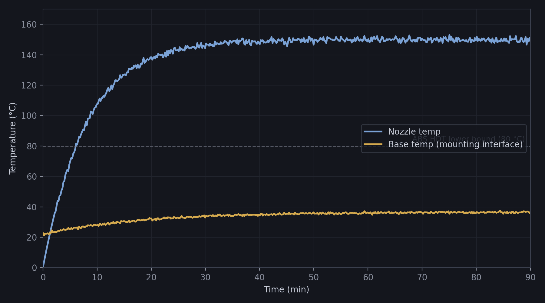
The enclosure is printed in ABS (HDT 80-100 °C); the extruder runs at 190-220 °C. The rebuild collapses if barrel heat softens the casing, so it was measured, not assumed: K-type thermocouples at the nozzle, mid-barrel, and mounting interface, read by MAX6675 modules and logged over sustained operation.
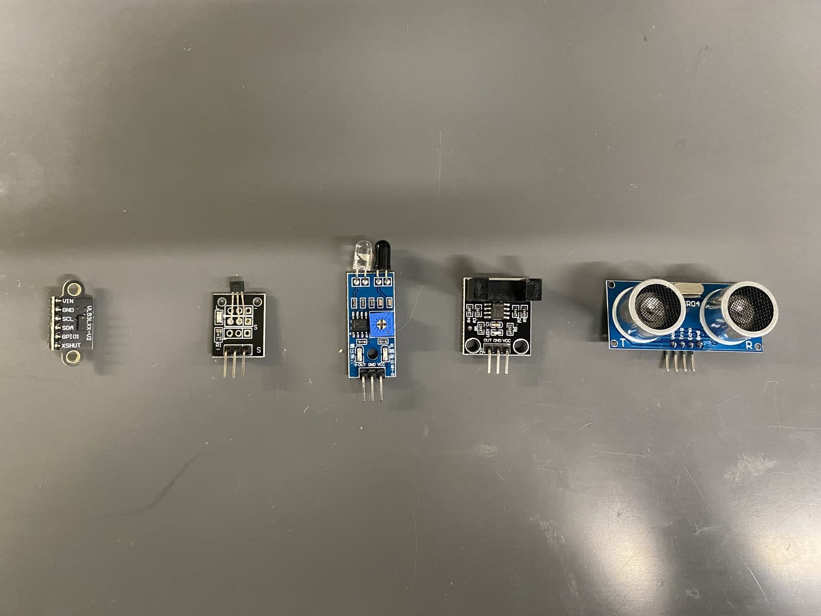
The requirement: detect a 1.75 mm filament moving fast, reliably, insensitive to ambient light and filament color, sub-second response. Four sensor candidates were evaluated experimentally with Arduino test rigs before settling on the LDR array: five photoresistors in a line, back-lit by a 1 W red line laser. Slack in the filament changes which LDRs the shadow crosses: a robust, color-independent, five-position tension signal.
That signal closes the loop: sensor → ESP32 → 5-level state machine (with debounce, speed ramping, and explicit fault states) → TMC2209 → winder speed. The winder holds filament tension at the sensor’s optimal level while extrusion proceeds independently: pellets in, spooled filament out.
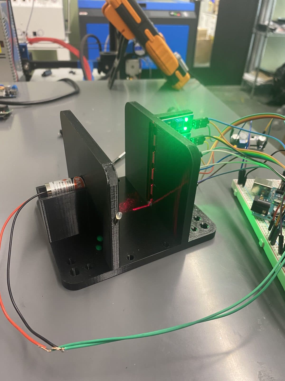
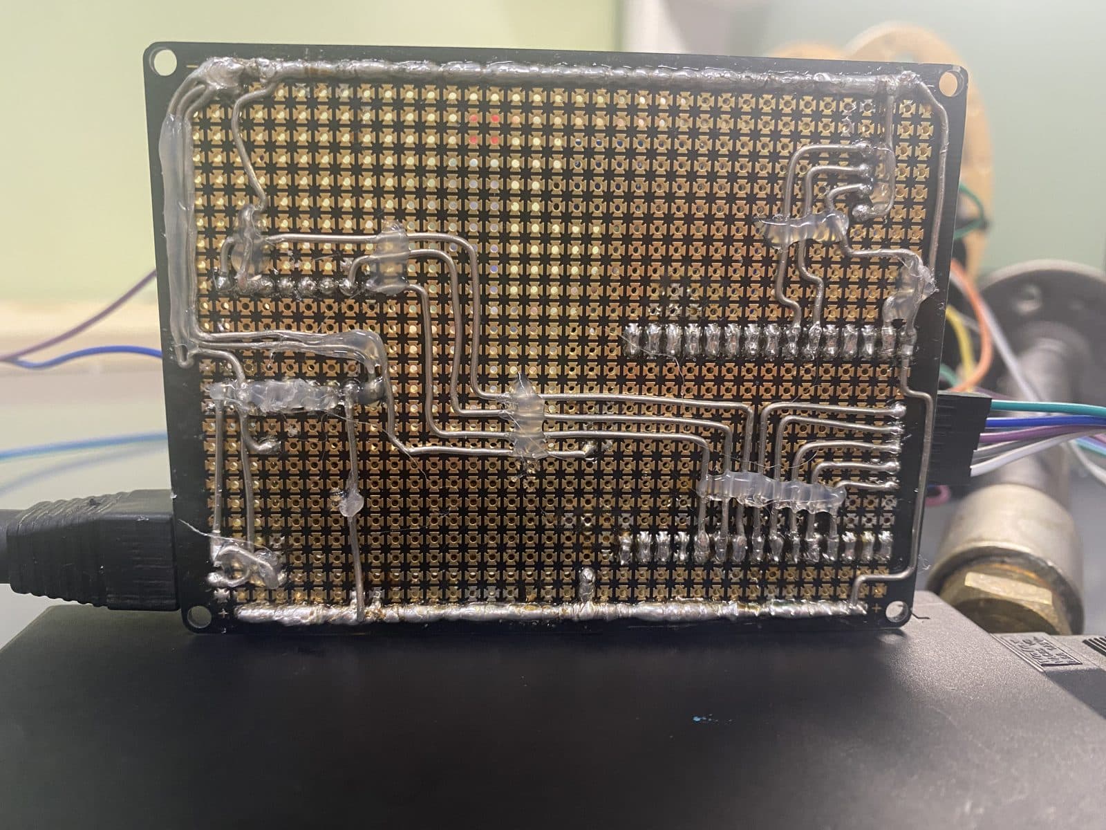
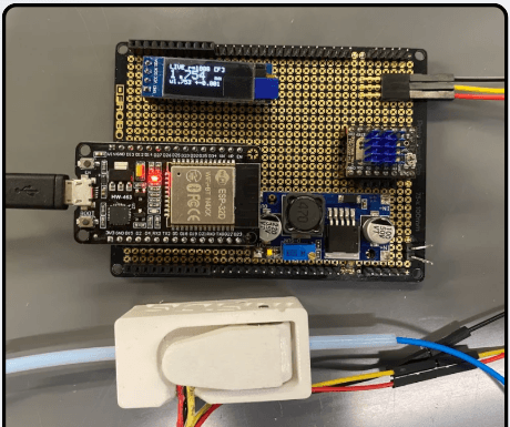
Slack sensing keeps the loop stable; a second optical module answers the research question that actually matters: is the filament 1.75 mm? The filament runs through a 3D-printed sensor housing where its shadow width sets how much light reaches the detector, and the ESP32 converts that reading into a live diameter figure. After correcting a 0.09 mm offset found against caliper control measurements, the sensor holds ~±0.03 mm precision, enough to catch the tension-induced diameter drift the verification tests exposed.
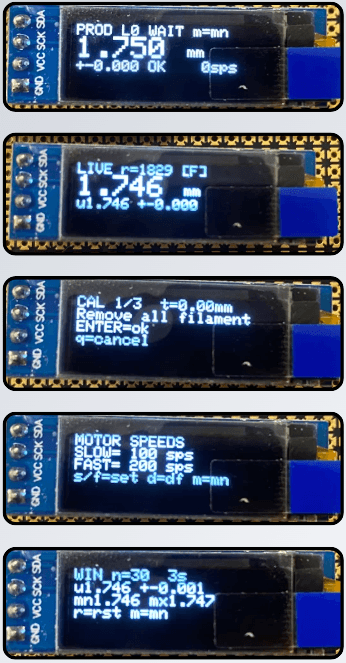
The firmware around it grew into a small instrument. An OLED menu system exposes five modes: Production (windowed average with a go/no-go readout), Live Diameter (raw reading at full sample rate), Calibration (a guided zero-and-reference routine), Motor Speed Config (slow/fast steps-per-second presets), and Session Statistics (min/max/mean over the run). Everything runs on the same non-blocking loop as the winder control, so menu navigation never stalls the motors.
Now: ~95% system integration; drafted IEEE-format paper; diameter-consistency characterization in progress. Sweeps across 190-220 °C and four motor speeds put the best extrusion at 195 °C at full motor speed, verified in two 20-minute runs on the automatic winder.
Planned hardware upgrades:a 12-bit ADC to sharpen the diameter sensor’s resolution, a status screen on the FilaStruder side, and a bearing-guided filament path to remove the tension-induced diameter drift.
Next research phase: magnetic and conductive composite filaments: NdFeB-loaded TPU for printed soft-robotic actuators. Every downstream actuator paper that uses custom filament traces back to this apparatus: it’s the methods section that makes the lab’s results reproducible.