CYCLOIDAL DRIVE · TMC2209/5160 · FUSION 360
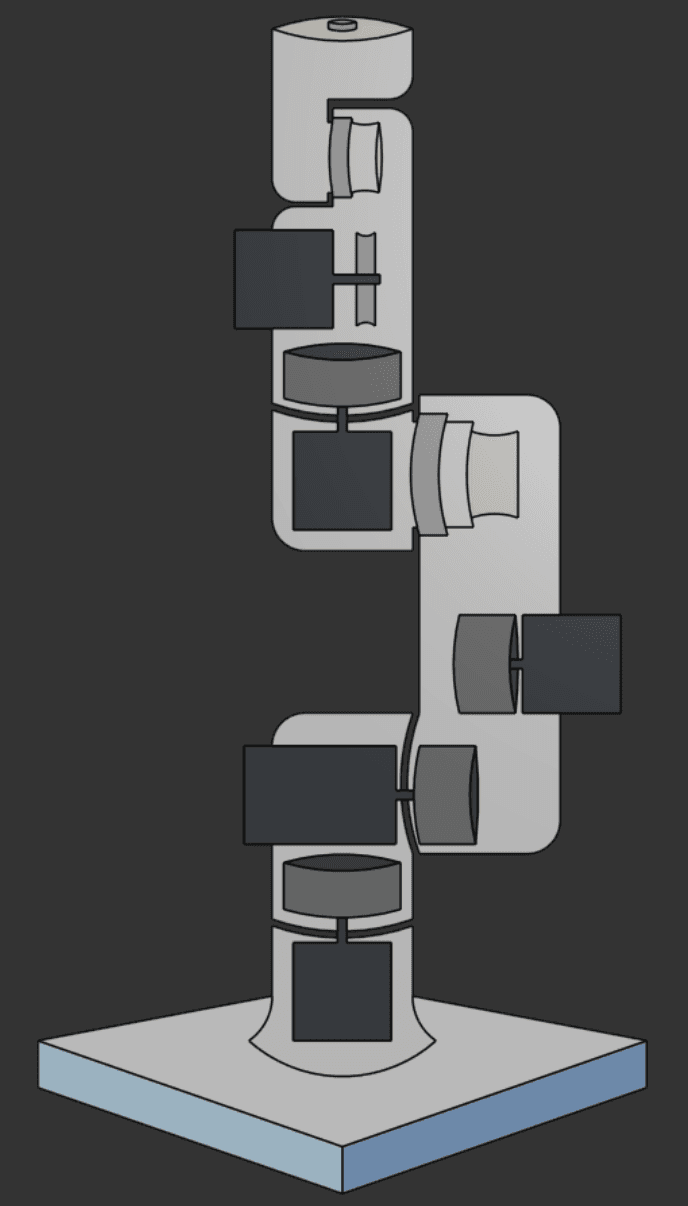
3D-printed robotic arm with cycloidal gearboxes and a tiered TMC2209 + TMC5160 stepper-driver architecture.
- REACH
- 50 cm · 6-DOF · <1 mm target
- TORQUE
- ~8.8 N·m at base (26:1, η≈0.85)
- DRIVES
- 3D-printed cycloidal · 26:1
- BRAINS
- ESP32 · TMC2209 UART + TMC5160 SPI
A fully scratch-built desktop robotic arm: 50 cm reach, 6 degrees of freedom, designed for <1 mm positional precision and 8 N·m of torque at the base. Every joint runs on a 3D-printed cycloidal gearbox designed and printed in-house. The control system uses an ESP32 driving a tiered stepper-driver architecture: TMC2209s over UART for the lighter wrist and elbow joints, TMC5160s over SPI for the high-torque base and shoulder. The firmware evolved across seven documented versions and includes a working diagnostic CLI, full DRV_STATUS fault decoding, and a fault-recovery routine.
The project pivoted mid-build: the first PCB concept was wired around planetary gearboxes. A video on a 26:1 cycloidal drive triggered a complete mechanical rethink. With no design files public, the drive had to be reverse-engineered from screenshots and motion principles.
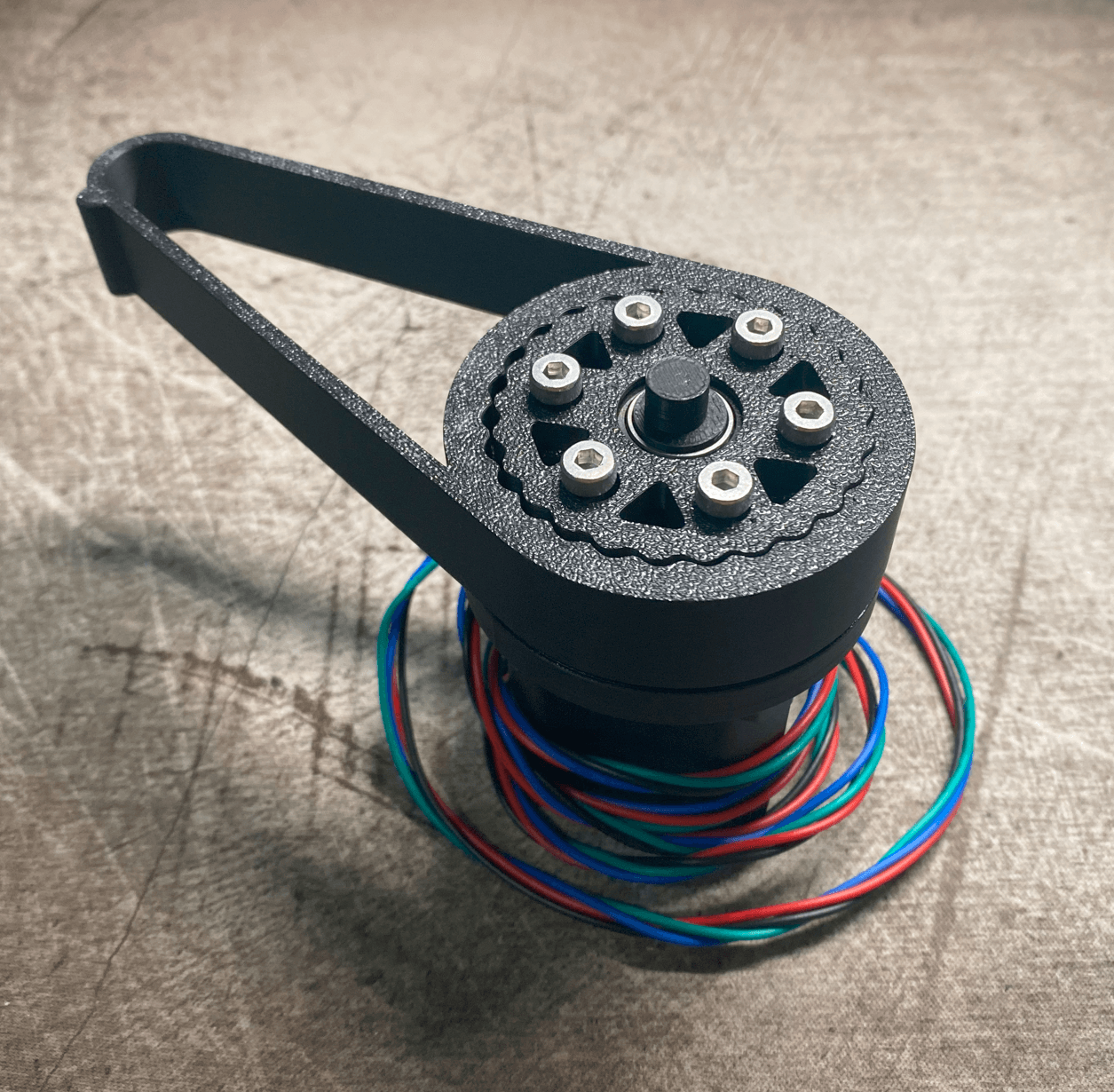
A cycloidal drive is a speed reducer where a disk wobbles inside a ring of pins. The disk has one fewer lobe than the ring has pins; each full input rotation advances the disk exactly one lobe in reverse. That single-tooth difference is the entire 26:1 reduction.
| PARAMETER | VALUE |
|---|---|
| Ring pins (P) | 27 |
| Disk lobes (L) | 26 |
| Gear ratio L/(P−L) | 26 : 1 |
| Output torque (NEMA 17, η ≈ 0.85) | ~8.8 N·m |
| Disks, 180° phased | 2 |
| Eccentric shaft | 10 mm, two 180°-offset lobes |
The dual-disk design, two cycloidal disks phased 180° apart on the eccentric shaft, is what gives serious cycloidal drives their near-zero backlash. As one disk moves away from a pin, the other moves toward it: the output is continuously driven from both sides, with no floating moment where the drive can rattle.
Why cycloidal? Harmonic drives win on every spec but need a spring-steel flex spline no FDM printer can make. Planetary carries 3-30 arc-min of backlash, too much for sub-mm work. Spur trains need 3-4 stages to reach 26:1 and cumulative backlash kills repeatability. Cycloidal is the only drive that hits the cost-vs-backlash sweet spot for a sub-mm hobbyist arm: $5-20 per drive, 0-3 arc-min with steel pins and roller bearings.
“We 3D-printed a cycloidal drive” sounds straightforward. In reality, printed drives have five well-documented failure modes, and the difference between a working drive and a one-week-then-fails drive is doing the upgrades before finding out which mode kills yours:
| # | FAILURE MODE | MITIGATION |
|---|---|---|
| 1 | Eccentric bearing-seat thermal softening (the #1 killer: seat spins at input speed, plastic passes Tg, bearing migrates) | High-Tg material: nylon / PA-CF (Tg ≈ 160 °C), not PLA (~55 °C) |
| 2 | Pin shear at layer lines under cyclic load | Never print pins: 304 stainless shoulder bolts (30-35 mm) |
| 3 | Disk delamination at the thinnest lobe section | Print disks flat, 4+ perimeters, concentric top/bottom layers |
| 4 | Fatigue wall ≈ 100,000 cycles (thermoplastics have no endurance limit) | Plan duty cycle: ~7 h continuous at 10 cycles/min |
| 5 | Viscoelastic heating: internal flexing heat, fails while cool to the touch | Material choice + duty-cycle headroom |
Tolerance reality: cycloidal drives want ±0.05 mm; consumer FDM realistically holds ±0.1-0.2 mm. The build uses the community-converged compensations: 0.3 mm lobe-pin design clearance, +0.05-0.07 mm hole horizontal expansion in the slicer, and bearing seats undersized ~0.1 mm for interference fit.
Most first builds pick one stepper driver and use it everywhere. Neither all-TMC2209 nor all-TMC5160 is right for a 6-DOF arm:
| JOINT ROLE | LOAD PROFILE | DRIVER | WHY |
|---|---|---|---|
| Wrist · elbow | Light: carries only gripper payload | TMC2209 (UART) | NEMA 17 at 24 V is sufficient; UART addressing lets 4 drivers share a 3-wire bus through rotating joints |
| Base · shoulder | Heavy: full inertial moment of every link above | TMC5160 (SPI) | 60 V ceiling, 20 A external-FET capability, integrated motion controller |
The TMC5160’s defining feature is its integrated motion controller: the MCU writes XTARGET once over SPI and the driver generates all 51,200 step pulses internally (ramping, cruising, decelerating) with zero MCU involvement. Wrist axes are limited by how fast the ESP32 can pulse STEP (hardware-timed via the RMT peripheral); base axes are limited only by SPI bandwidth. The two driver layers run in parallel without contending for the same MCU resources. That’s what lets one ESP32 run six axes without the per-axis ISR contention that kills naive multi-axis builds.
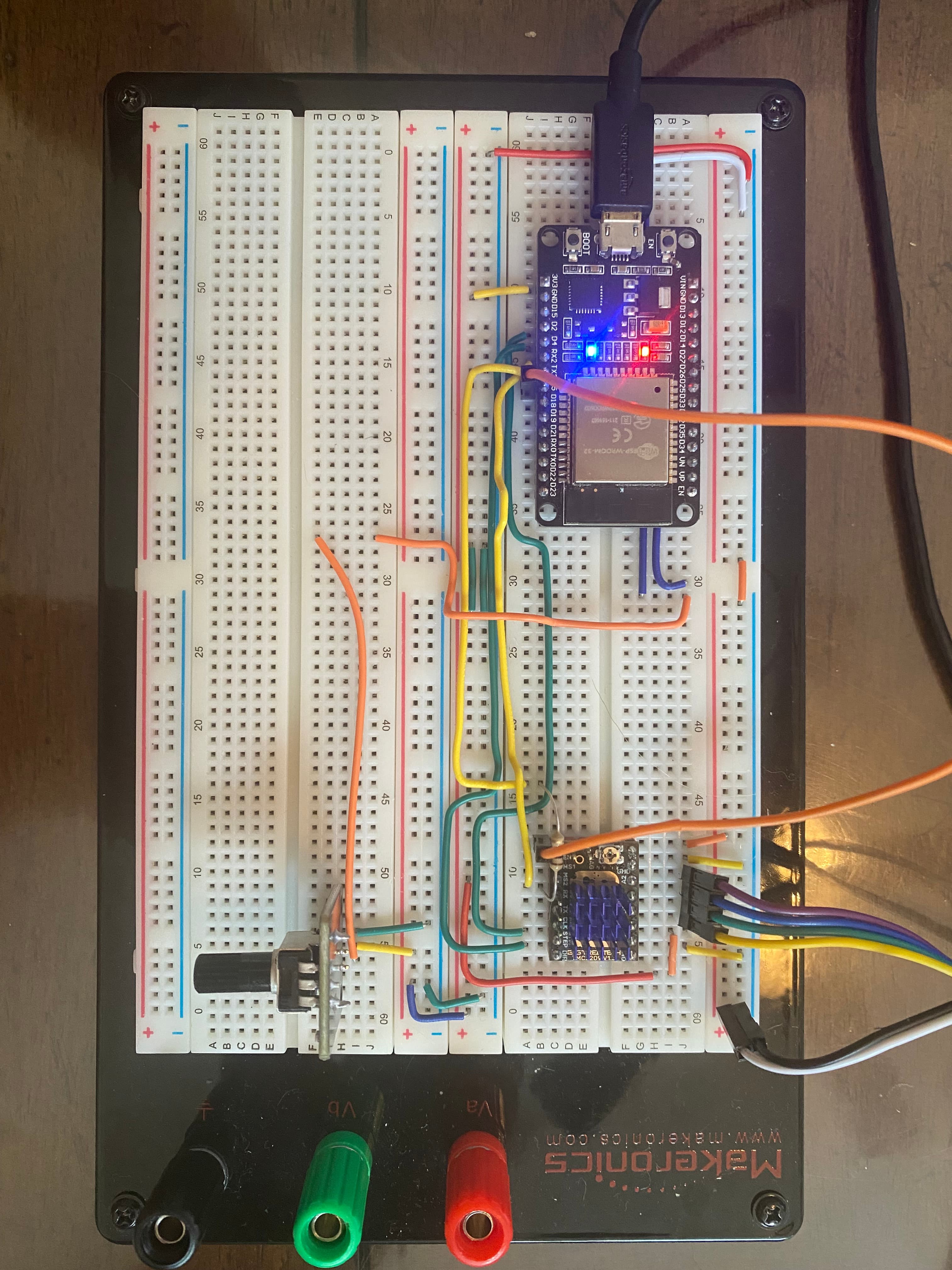
StallGuard replaces endstops entirely: both drivers infer mechanical load from back-EMF, so homing means driving each joint into its hard stop and watching the DIAG pin: no microswitches, no extra wiring through six rotating joints. The trade is careful SGTHRS tuning: calibrated unloaded, it false-triggers under payload, so it’s tuned at maximum expected payload with headroom.
Seven documented firmware versions trace an arc from first UART contact to a multi-file PlatformIO architecture. V1.0 already shipped with a serious diagnostic CLI: diag · status · reconfig · step · current · gconf? · faults plus a 15-attempt write-and-verify retry loop for stubborn UART registers.
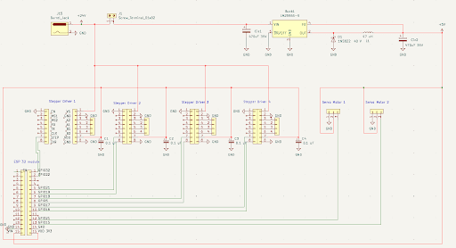
Built and working: cycloidal drive V1 printed and assembled · ESP32 + TMC2209 firmware through V1.3 with CLI, fault detection and recovery · PlatformIO multi-file refactor · first-pass KiCad PCB.
Open: multi-motor UART addressing · TMC5160 SPI integration for base/shoulder · Bluetooth command protocol · drive efficiency and backlash measurements · PCB redesign with proper buck sizing · ROS/AI integration hooks.